




A Must-Have Tool for Electronics Repair Engineers: How Thermal Cameras Identify Overheating Issues in PCBs, Chips, and Electronic Components


Electronic devices are becoming smaller, faster, and more powerful. At the same time, managing heat has become increasingly important as electronic components operate at higher power densities and within increasingly compact spaces. A PCB may appear perfectly normal to the naked eye, yet a specific chip, capacitor, resistor, connector, or circuit path on the board could be operating at an abnormal temperature.
This is where thermal cameras for electronics repair become useful. Instead of relying only on electrical measurements or visual inspections, engineers can use thermal imaging technology to visualize the distribution of heat across the circuit board.
For PCB troubleshooting, thermal imaging provides a quick way to locate abnormal heat and narrow down possible component problems.
Why Overheating in Electronic Devices Is Critical
Abnormal heat generation is a common sign of electrical or component problems.
An abnormal rise in a component's temperature may be associated with excessive current, high resistance, poor contact, a short circuit, or an internal fault. In some cases, the heat is a result of another component or circuit nearby.
The challenge is that these conditions often cannot be detected by the naked eye.
A damaged component may appear perfectly normal yet exhibit significant temperature anomalies. Thermal imaging cameras for PCB inspection allow these temperature differences to be detected without touching the circuit board.
How Thermal Cameras Locate Overheating Components
Thermal cameras detect infrared radiation emitted from the surface of electronic devices and convert it into thermal images.
When a PCB is operating, different components naturally produce different amounts of heat. Thermal images allow engineers to compare these areas.
For example, if several similar components operate at comparable temperatures but one is significantly hotter, that specific component warrants further inspection.
This makes thermal imaging especially useful during troubleshooting because engineers can quickly move from a large circuit board to a specific area.
Detecting Overheating on PCBs
PCBs contain many components packed into a relatively small space.
A thermal camera can scan the board while it is operating and show where heat is concentrated.
Engineers can use thermal imaging technology to inspect the following components and circuit features:
l Resistors
l Capacitors
l Diodes
l MOSFETs
l Voltage regulators
l Connectors
l Power components
l PCB traces
A hotspot does not automatically mean the component is defective. However, abnormal temperature differences often provide crucial clues for pinpointing the location of a fault.
Identifying Chip and IC Faults
Integrated circuits can be difficult to troubleshoot because many of their functions are hidden inside a small package.
If an IC develops an internal fault or operates under abnormal electrical conditions, the resulting abnormal heat generation may appear as a localized hotspot on its surface.
Using thermal imaging technology, engineers can compare the temperature of a suspected faulty chip with that of surrounding components or a properly functioning PCB.
A localized hotspot on or around an IC can therefore provide a useful starting point for further electrical testing.
Detecting Short Circuits and Abnormal Current Paths
Short circuits can generate localized heat.
When current flows through an unintended path, the affected component, trace, or connection may become warmer than surrounding areas.
Engineers can use thermal cameras to identify these thermal signatures while the circuit board is powered.
This method is particularly effective when faulty components are difficult to identify through visual inspection.
Once a hotspot is located, the engineer can combine the thermal result with circuit diagrams, resistance measurements, voltage measurements, and other diagnostic methods.
Inspecting Power Components
Compared to low-power components, power-related components typically generate more heat.
MOSFETs, voltage regulators, power resistors, inductors, and other components may become warm during normal operation. The key factor is whether their temperature aligns with expected operating conditions.
Using thermal imaging technology, engineers can compare similar components and observe the distribution and conduction of heat across the circuit board.
An abnormal hotspot can indicate that a component should be checked more closely.
Thermal Cameras Can Also Help During Repair Verification
Thermal imaging technology is not only useful for finding problems.
After replacing damaged components, engineers can operate the PCB again and compare the new thermal image with the original results.
If abnormal hotspots disappear or the temperature distribution returns to the expected state, this provides useful evidence that the repair has effectively resolved the issue.
Thermal images can also be saved as inspection records for future comparison.
What Engineers Should Look for in a Thermal Camera
For the inspection of PCBs and electronic components, engineers should focus on the following factors:
l Thermal resolution
l Thermal sensitivity
l Close-up imaging capability
l Temperature measurement accuracy
l Focus performance
l Image stability
l Measurement and analysis functions
Sufficient image detail is required when inspecting tiny components. Good thermal sensitivity is also important when the temperature difference between a normal component and a suspicious component is relatively small.
Guide Thermal Cameras for Electronics Inspection
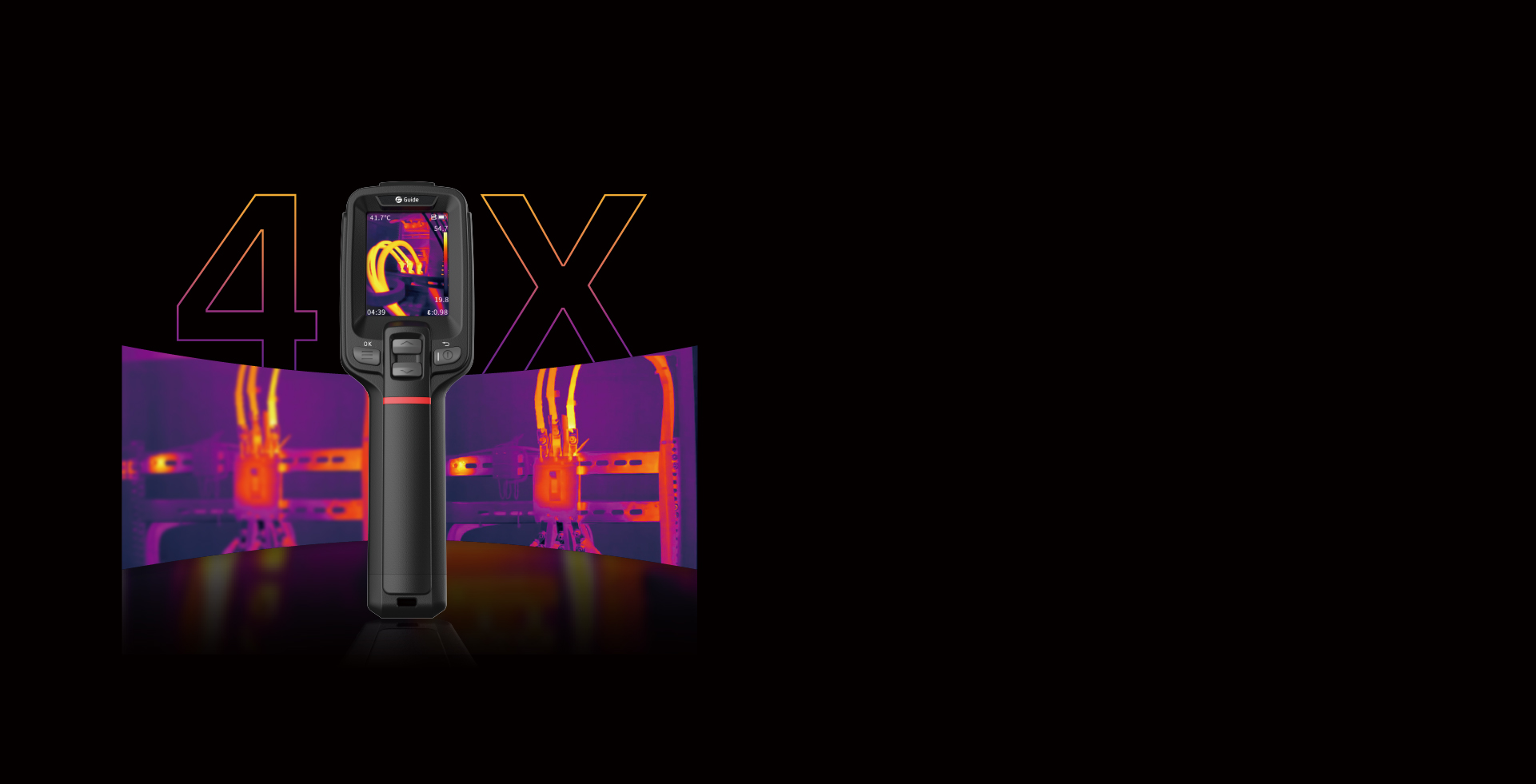
Guide specializes in the R&D and manufacturing of thermal imaging cameras for various professional fields. Its product portfolio includes handheld thermal cameras, thermal cameras for smartphone, Acoustic & Thermal Imaging Camera, firefighting thermal cameras, and VOCs detection thermal cameras.
For electronics engineers, portable thermal cameras and thermal camera for smartphone can provide a convenient way to inspect PCBs, chips, connectors, and other components during troubleshooting and maintenance.
Thermal information can be combined with electrical measurements and circuit knowledge to help engineers locate problems more efficiently.
Conclusion
Thermal cameras for electronics repair are practical tools for identifying abnormal heat generation in PCBs, chips, and electronic components.
They enable engineers to locate hotspots, compare component temperatures, troubleshoot potential short circuits, check power components, and verify repair results.
Thermal imaging does not replace electrical testing; instead, it provides an additional dimension of information, making troubleshooting faster and more targeted.
For engineers working with increasingly compact and complex electronics, seeing where heat is generated can be an important step toward finding the real cause of a circuit problem.
.jpg)
-944.jpg)


